CMU 18741 Computer Networks F24 学习笔记
文章目录
Lecture 1: Course Overview
- Network: An infrastructure that allows (distributed) “users” to communicate with each other + It is assumed that the infrastructure is shared by many users
- Network architecture: the plan that specifies how the network is built and operated
- different stage in the evolution of telecommunications technology
- Message Switching Architecture: message is stored and forwarded by intermediate nodes (or switches) in the network until it reaches its destination
- Network nodes: where several lines met
- Store-and-Forward Operation:
- Messages were decoded
- Next-hop in route determined by destination address of a message
- Each message was carried by hand to next line
- Circuit Switching
- Connection set up: Source first establishes a connection (circuit) to destination
- Each switch along the way stores info about connection (and possibly allocates resources)
- Information transfer: Source sends the data over the circuit
- No need to include the destination address with the data since the switches know the path
- Connection release: The connection is explicitly torn down
- (+) fast and simple data transfer once the circuit is established; predictable performance e.g. guaranteed bandwidth
- (-) bursty traffic that circuit be idle for significant periods of time? user have different bandwidth needs?
- Connection set up: Source first establishes a connection (circuit) to destination
- the Internet, i.e. (Packet) Switching
- Source sends information as self-contained messages that have an address
- Source may have to break up single message in multiple packets
- Each packet travels independently to the destination host
- Switches use the address in the packet to determine how to forward the packets
- Store-and-forward
- (+) General for many apps; Efficient, robust resource sharing
- (-) Lack of isolation: congestion, variable delay, etc.
- Source sends information as self-contained messages that have an address
- Message Switching Architecture: message is stored and forwarded by intermediate nodes (or switches) in the network until it reaches its destination
- the Internet
- inter-net: network of networks
- Networks are connected using routers and other devices
- The Internet: the interconnected set of networks of the Internet Service Providers (ISPs)
- objective: enable communication between diverse applications on diverse devices, over diverse infrastructures
- Internet design
- In order to inter-operate, all participating networks must follow a common set of rules (standards)
- service model: best-effort (packets can get lost, etc.)
- inter-net: network of networks
- Packet Switching - multiplexing
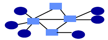
- Interior nodes act as “Switches”
- Switches arbitrate between inputs + Can send from any input that’s ready
- Links are never idle when there is traffic to send (Efficiency!)
- Need to share network resources (challenges: fairness, efficiency, …)
Lecture 2: Protocol Stack
-
Application, Application Protocols
- Applications are programs that communicate and operate across different network hosts (distributed processes), often in the user space of a system. They exchange messages to perform tasks, such as sending emails, transferring files, or browsing the web
- Application protocols are components of these applications that define how the messages are exchanged and what actions should be taken in response.
- Client-Server Paradigm
- Client: Initiates contact with server (“speaks first”), Typically requests service
- Server: Provides a service to client
-
Packet Delay
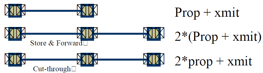
- store-and-forward vs. cut-through
- components
- Propagation delay on each link - Proportional to the length of the link
- Transmission delay on each link - Proportional to (the packet size) and (1 / link speed)
- Processing delay on each router - Depends on the speed of the router
- Queuing delay on each router - Depends on the traffic load and queue size
- store-and-forward vs. cut-through
-
Application-level Delay
- fixed / throughput dependent delay
- = delay of one packet + size / throughput
-
Throughput
- is determined by slowest link in the network (bottleneck link)
- Throughput vs. bandwidth: Throughput can never exceed bandwidth; it is typically lower due to various inefficiencies or network conditions.
- Bandwidth Sharing
- Router before the bottleneck link decides how much bandwidth each user gets
- Users that try to send at a higher rate will see packet loss
- User bandwidth can fluctuate quickly as flows are added or end, or as flows change their transmit rate
- Router before the bottleneck link decides how much bandwidth each user gets
- Bandwidth Sharing
-
Protocol
- An agreement between parties on how communication should take place
- Module in layered structure
- Protocols define: Interface to peer (syntax & semantics)
- Actions taken on receipt of a messages
- Format and order of messages
- Error handling, termination, ordering of requests, etc.
-
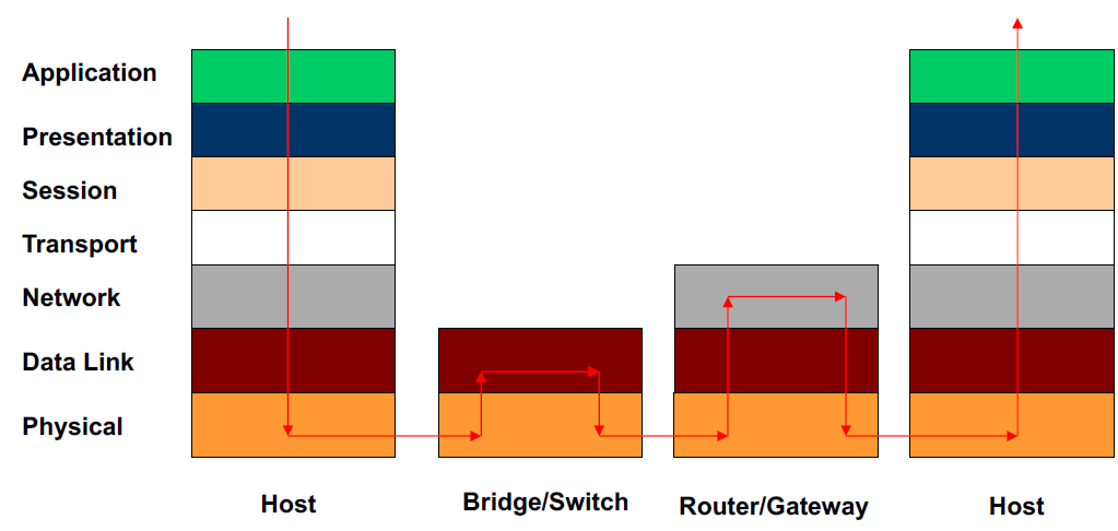
The Open Systems Interconnection (OSI) Model
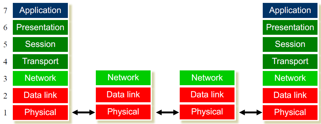
- Each layer relies on services from layer below and exports services to layer above
- Interface defines interaction with peer on other hosts – called protocols
- Modules hide implementation
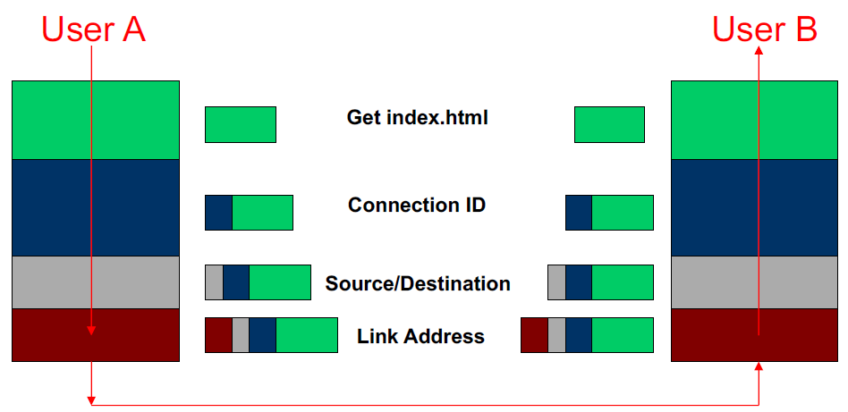
- Life of packet: down-up-down-up
- Layer encapsulation: fatter-slimmer
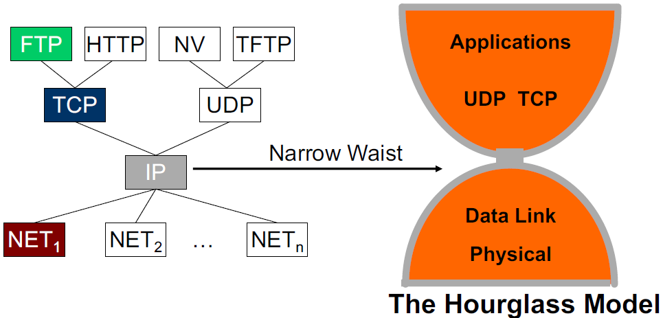
- Multiplexing and Demultiplexing
- There may be multiple implementations of each layer
- Each header includes a demultiplexing field that is used to identify the next layer
- Filled in by the sender & Used by the receiver
- There may be multiple implementations of each layer
Lecture 3-5: Physical Layer
1. Digital Modulation
- Analog vs. Digital Information
- Analog information takes on continuous values
- Sound, images, etc.
- Digital information takes on discrete values
- Text, banking data, etc.
- Can convert between the two representations of information – Sampling and interpolation
- Analog information takes on continuous values
- Block vs. Stream Information
- Block: Information that occurs in a single block
- Text message, Data file, JPEG image, MPEG file
- Stream: Information that is produced & transmitted continuously
- Real-time voice, Streaming video
- Block: Information that occurs in a single block
- why use a Single Digital Network
- digital: Computers operate only on digital data
- digital: Digital transmission can recover from errors (e.g. noise, distortion)
- single: economically advantageous
- Analog vs. Digital Transmission
- Transmission: distortion + attenuation
- Analog: All details must be reproduced accurately
- repeater: attempts to restore analog signal to its original form

- limitation:
- Restoration is imperfect: Distortion is not completely eliminated; Noise & interference is only partially removed
- Signal quality decreases with # of repeaters
- Communications becomes distance-limited
- Digital: Only discrete levels need to be reproduced
- regenerator: recovers original data sequence and retransmits on next segment

- Can design so error probability is very small - error-less long-distance communication
2. Error Control
- Two basic approaches:
- Error detection & retransmission (ARQ): errors in data transmission are detected by the receiver, and the sender is requested to retransmit the erroneous data
- Forward error correction (FEC): the receiver detect and correct errors, without needing retransmission
- Key Idea of error detection
- All transmitted data blocks (“codewords”) are chosen so that they satisfy a pattern; If received block doesn’t satisfy pattern, it is in error
- Redundancy: Only a subset of all possible blocks can be valid codewords
- Undetectable Error: When channel transforms a codeword into another valid codeword
- in practice: a combination of the two
- Parity Check
- Single Parity Check
- Redundancy: overhead =
- Coverage: all error patterns with odd # of errors
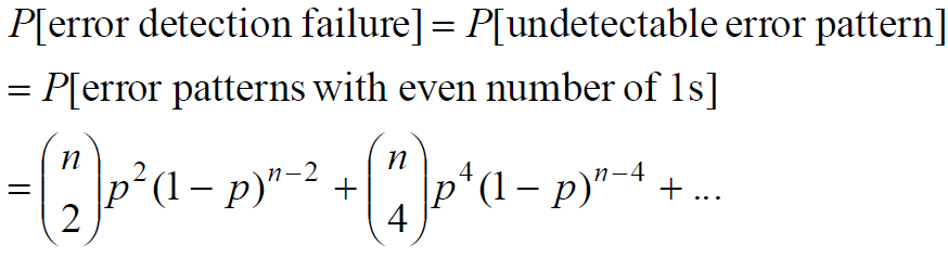
- Undetectable Error: All even-numbered error patterns are undetectable
- with bit errors at random, P[undetectable error] < 0.5
- with bit errors at random, P[undetectable error] < 0.5
- Redundancy: overhead =
- Two-Dimensional Parity Check
- 1 error can always be corrected
- 1, 2, or 3 errors can always be detected
- Not all patterns >4 errors can be detected
- Single Parity Check
- Internet Checksum
- Treating each 16-bit word as an integer (
), the Internet checksum - carried out in software using one’s complement arithmetic
- Treating each 16-bit word as an integer (
- CRC (cyclic redundancy check)
- polynomial coding
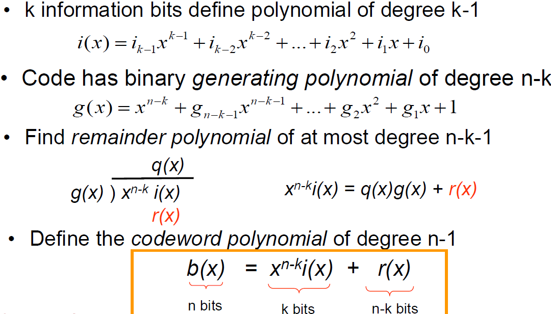
- pattern: All codewords are a multiple of
- Undetectable Error: if the error
is a multiple of - use primitive polynomials to minimize undetectable error
- polynomial coding
- Hamming Codes
- Capable of correcting all single-error patterns
- Redundancy:
- example:
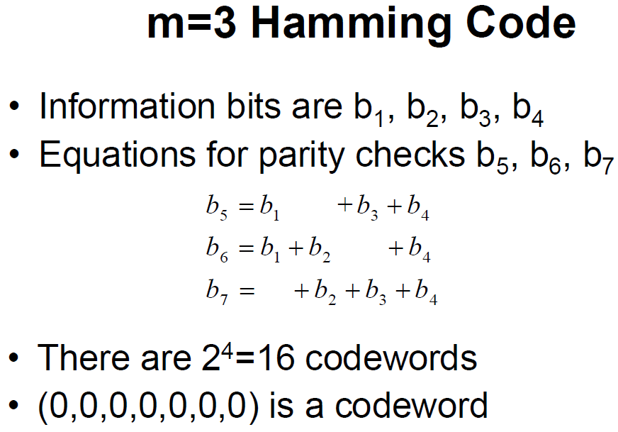
- Correction:
- Two valid bit sequences have a minimum distance of 3 bit flips
- Spheres of distance 1 around each codeword do not overlap - If a single error occurs, the resulting n-tuple will be in a unique sphere around the original codeword - receiver can correct erroneous reception back to original codeword
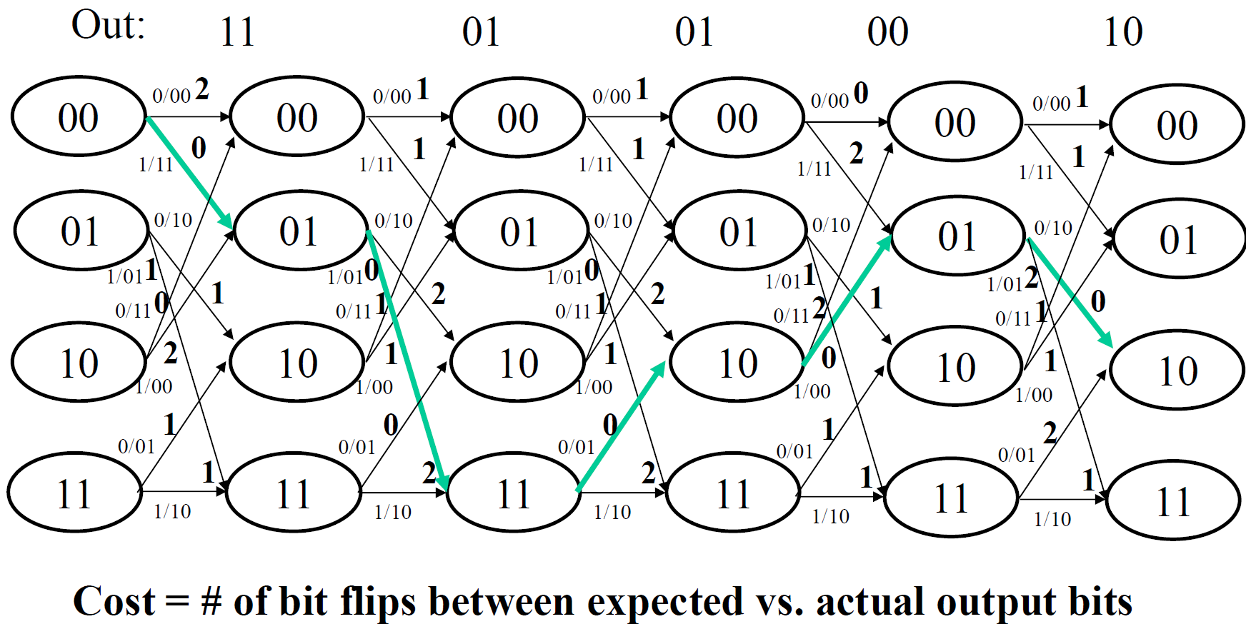
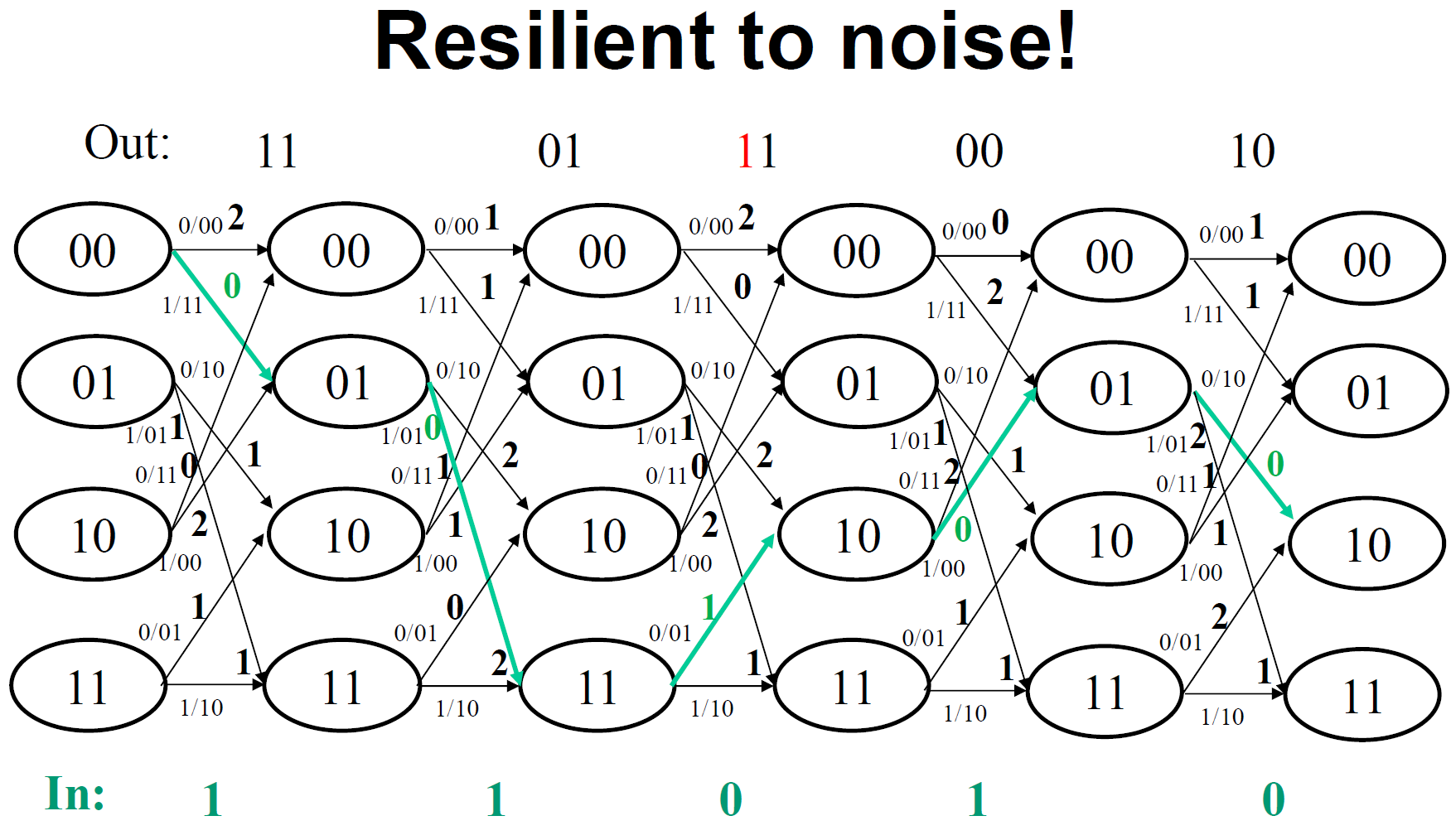
- Convolutional Codes
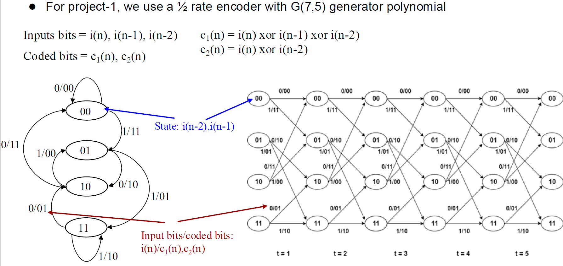
- encoding:
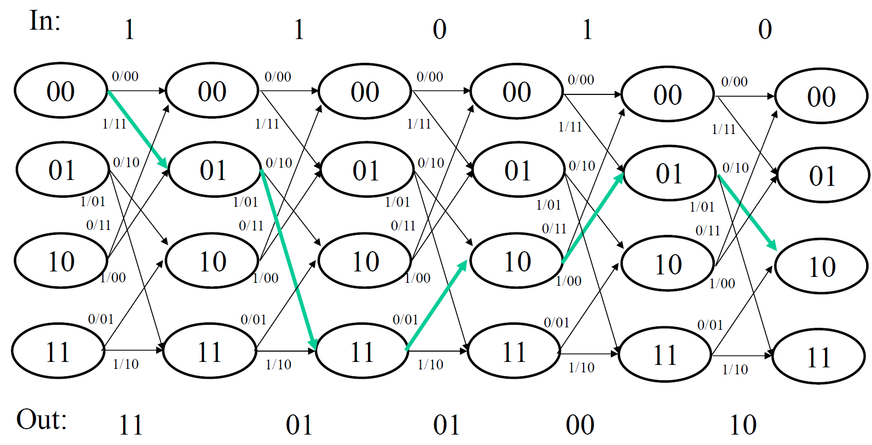
- decoding:
3. From Signals to Packets: Modulation
- Modulation: changing a signal to convey information
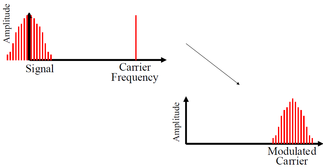
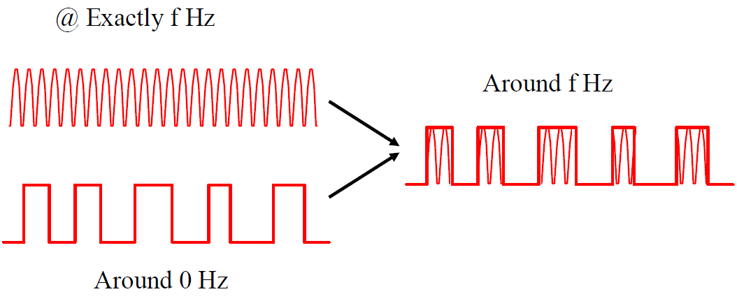
- The method: carrier modulation
- generate signal around lower frequency and move it to higher frequency
- generate signal around lower frequency and move it to higher frequency
- Amplitude Modulation (AM) (Volume)
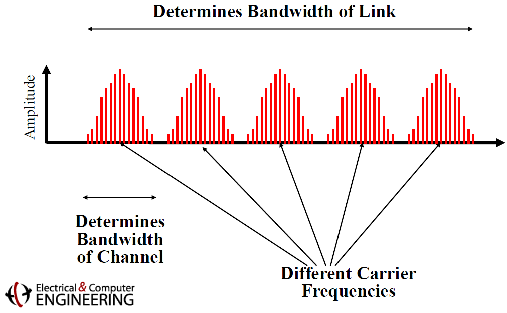
- frequency division multiplexing
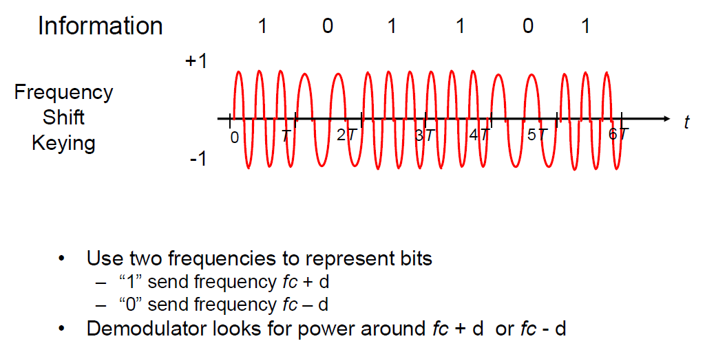
- Frequency Modulation (FM) (Pitch)
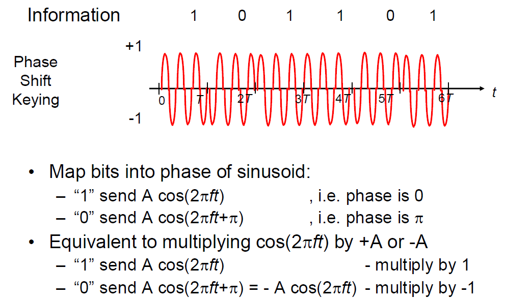
- Phase Modulation (PM) (Timing)
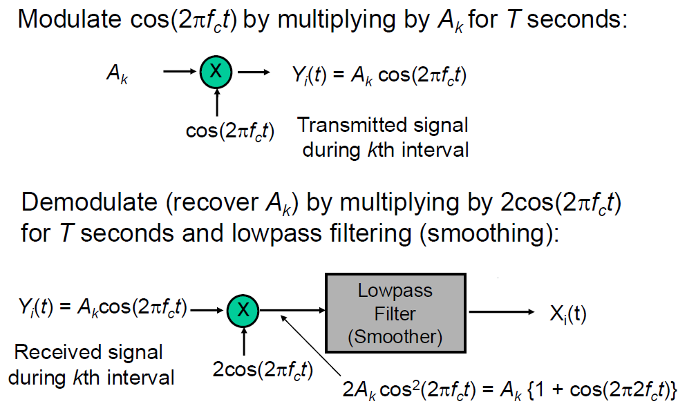
- modulator & demodulator:
- The method: carrier modulation
- Quadrature Amplitude Modulation (QAM)
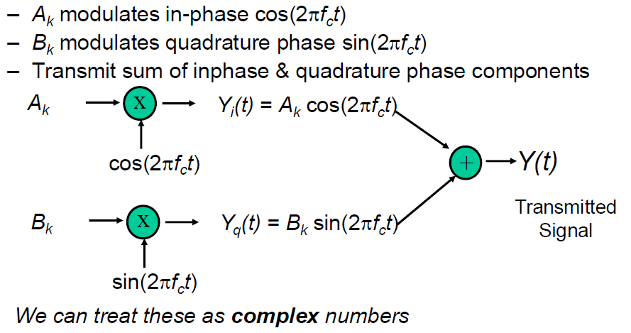
- 2-dimensional signaling
- modulation:
- demodulation:
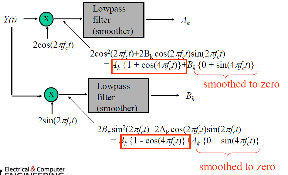
- signal constellations: n bits/pulse -> 2^n points on the plane
- QAM combines amplitude modulation and phase modulation
- FDM (frequency division multiplexing) & OFDM
- solved problem:
- multipath interference: In wireless and wired communication, signals often reflect off buildings, objects, or other surfaces, creating multiple delayed versions of the signal arriving at the receiver at slightly different times. This can cause inter-symbol interference (ISI), where overlapping signals interfere with each other, leading to data loss
- attenuation + phase shift
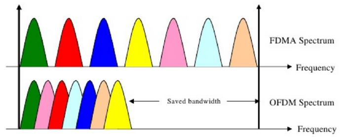
- available bandwidth is divided into multiple smaller sub-carriers (each with a lower data rate => longer symbol duration), each carrying a portion of the data in parallel
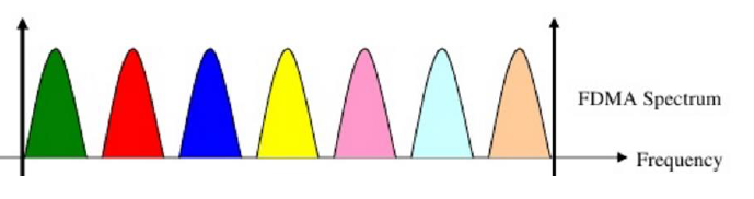
- OFDM: Orthogonal frequency division multiplexing: Get rid of guard bands by “orthogonal” frequency division
- solved problem:
4. Characterization of Communication Channels & Fundamental Limits in Digital Transmission
- Bandwidth: width of the frequency range where it is above some threshold value (the Fourier transform of the signal is non-zero)
- transforming a signal from the time domain (where we observe variations over time) to the frequency domain (where we observe variations in frequency components)
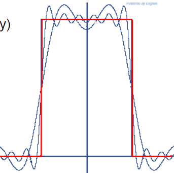
- A (periodic) signal can be viewed as a sum of sine waves of different strengths
- Every signal has an equivalent representation in the frequency domain (i.e. can be transformed into its equivalent frequency representation): what frequencies are present+ their strength (energy)
- Transmission Channel Considerations
- higher frequency signals experience more power loss
- medium: Every medium supports transmission in a certain frequency range. Outside this range, effects such as attenuation, … degrade the signal too much
- Limits to Speed and Distance => Effects limit the data rate that a channel can sustain, effects become worse with distance
- Noise: “random” energy is added to the signal.
- Attenuation: some of the energy in the signal leaks away.
- Dispersion: attenuation and propagation speed are frequency dependent (Changes the shape of the signal)
- Pulse Transmission Rate
- If pulses’ amplitudes are either -A or +A, then each pulse conveys 1 bit, so Bit Rate = 1 bit/pulse x 2Wc pulses/sec = 2Wc bps
- Multi-level Pulse Transmission: By going to M=2^m amplitude levels, we achieve Bit Rate = m bits/pulse x 2Wc pulses/sec = 2mWc bps
- In the absence of noise, the bit rate can be increased without limit by increasing m
- Capacity of a Noiseless Channel - The Nyquist Limit: A noiseless channel of width H (bandwidth H) can at most transmit a binary signal at a rate 2 x H, Assuming binary amplitude encoding
- Capacity of a Noisy Channel - Shannon’s theorem: C = B x log2(1 + SNR)
- C: maximum capacity (bps), B: channel bandwidth (Hz), SNR: signal to noise ratio of the channel
- if the transmission rate R < C, Arbitrarily-reliable communications is possible => the Bit Error Rate can be made arbitrarily small through sufficiently complex “coding”
Lecture 6-9: Data Link Layer
1. Synchronization
- Asynchronous transmission: data is sent one byte or character at a time, with each byte or character being independently synchronized
- Avoids synchronization loss by
- specifying a short maximum length for the bit sequences (so that clock doesn’t drift much within sequence)
- and resetting the clock in the beginning of each bit sequence
- Avoids synchronization loss by
- Synchronous transmission: data is sent in continuous blocks (frames or packets) with the sender and receiver being synchronized to a shared clock signal
- Overcomes the inefficiency of asynchronous transmission.
- Improves efficiency by transmitting longer sequences of bits, called packets (variable length).
- Requires extra information to indicate the end of the packet.
2. Encoding
- Encoding converts a binary information sequence into a digital signal
- Encoding can be done one bit at a time or in blocks of multiple bits called a symbol
- Transmission is synchronous, i.e., a clock is used to sample the signal
- need of encoding: error detection / correction
- mB/nB Encoding
- m data bits are coded as symbols of n line bits
- e.g. 4B5B
- Each valid symbol has at least two 1s: get dense transitions
- 16 data symbols - 4 data bits
- 8 control symbols - idle, begin frame, etc
3. Framing
- Framing: a fundamental function of the data link layer. It involves defining the boundaries of the data being transmitted over a network. Specifically, framing establishes which bits have which function, such as identifying the start and end of a data packet.
- Framing technique
- Out of band delimiters (e.g. 4B/5B control symbols)
- delimiter characters e.g. SYN, SOH, STX, ETX
- Character and Bit Stuffing: when delimiter characters / bit sequences is in body: mark frames with special character / bit sequence, e.g. escape character, transmitter inserts a 0 when delimiter appears in the data, must stuff a zero any time seven 1s appear
- delimiter characters e.g. SYN, SOH, STX, ETX
- Synchronous transmission (e.g. SONET) - Boundaries are based on timing
- Ethernet Framing: Preamble is 7 bytes of 10101010 (5MHz square wave) followed by one byte of 10101011
- Out of band delimiters (e.g. 4B/5B control symbols)
4. Flow Control and Error Recovery
- Stop and wait flow control: Max Throughput = 1 pkt size / RTT
- Window flow control: Max Throughput = window size * pkt size / RTT
- Window size: # of total outstanding packets that sender can send without acknowledged
- window size: For m-bit sequence number:
- Error recovery: frame level (vs. physical layer: bit level)
- Error Correcting Codes (ECC): Send extra redundant data to help repair losses
- Automatic Repeat Request (ARQ): Receiver sends acknowledgement (ACK) when it receives packet
5. Datalink architectures
- Switches connected by point-to-point links - store-and-forward
- Multiple access networks - contention based: Multiple hosts are sharing the same transmission medium
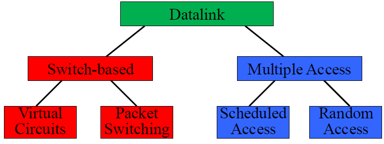
- Multiple Access - Scheduled Access: Reservation system
- centralized system vs. distributed systems
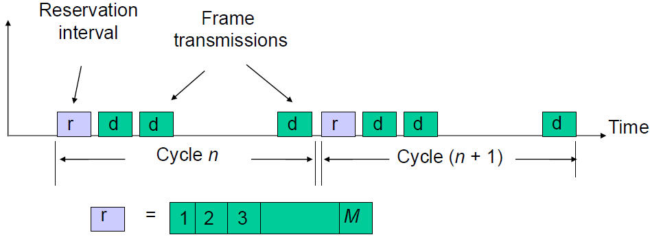
- Transmissions organized into cycles
- Cycle: reservation interval ® + frame transmissions (d d d …)
- Reservation interval: This is the portion of the cycle where stations (or nodes) send reservation requests to indicate that they want to transmit data in the upcoming frame transmission period. Each station has a mini-slot in this reservation interval where it can signal its intention to transmit.
- Frame transmission period (d, d, d, …): This is the part of the cycle where data frames from different stations are actually transmitted. Each frame corresponds to data being sent by a station that successfully made a reservation during the reservation interval
- Reservation interval has a mini-slot for each station (fixed length, M) to request reservations for frame transmissions
- Single or Multiple Frames: Only one / More than one frame transmission can be reserved within a cycle
- Channelized or Random Access Reservations
- Channelized : Reservation messages from different stations are multiplexed without any risk of collision
- Random access reservation: Each station transmits its reservation message randomly until the message goes through. i.e., Aloha used during reservation period
- Example: Cellular 4G / 5G: frequency & time reservation
- Multiple Access - Random Access Protocols
- When node has packet to send: Transmit at full channel data rate R
- No a priori coordination among nodes
- Two or more transmitting nodes => “collision”
- Random access MAC protocol specifies: (1) How to detect collisions (2) How to recover from collisions (e.g., via delayed retransmissions)
- Multiple Access - Random Access: ALOHA
- Basic idea: When you are ready, transmit; Receivers send ACK for data; Detect collisions by timing out for ACK; Recover from collision by trying after random delay
- collision:
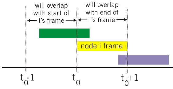
- Pkt sent at t_0 collide with other pkts sent in [t_0-1, t_0+1]
- Window of vulnerability is roughly 2 packets
- Poisson Process
- independent increments in disjoint intervals
- The increments of the process are stationary: start time does not matter
- The probability of exactly one event occurring in an infinitesimal interval
is - The probability that more than one event occurs in any infinitesimal interval
is - The probability of zero events occurring in
is
- Poisson distribution:
- mean:
, variance: - inter-arrival time: with CDF
, with probability density function , , - merging Poisson Process:
- splitting Poisson Process:
- mean:
- Pure ALOHA: traffic intensity / network throughput
where N station , packets/sec, package length fixed at m - With retransmission (
): - Maximum Throughput:
=> S is maximum at at
- With retransmission (
- Slotted ALOHA
- Time is divided into equal size slots Equal to packet transmission time
- Node (w/ packet) transmits at beginning of next slot
- If collision: retransmit pkt in future slots with probability p, until successful
- since Window of vulnerability is 1 instead of 2, Maximum Throughput
at
- since Window of vulnerability is 1 instead of 2, Maximum Throughput
- Maximum throughput is low for both variants
- Slotted Aloha can achieve higher throughput
- But has higher latency, especially under low load
- Wifi CSMA: Sort-of ALOHA
- pick a random interval to wait for and then transmit
- Important idea: Exponential backoff, random interval increases exponentially
- Key difference: “Listen” (carrier sense) and stop your “count down clock” if any transmission is detected
- Multiple Access - Random Access: Ethernet
- Sending adapter encapsulates IP datagram (or other network layer protocol packet) in Ethernet frame
- Preamble: 8 bytes - Used to synchronize receiver, sender clock rates
- CRC: 4 bytes – Checked at receiver, if error is detected, the frame is simply dropped
- Type: 2 bytes – Demultiplexing: indicates the higher layer protocol
- Addressing Alternatives
- Broadcast: all nodes receive all packets
- Addressing determines which packets are kept and which are packets are thrown away
- Packets can be sent to:
- Unicast – one destination
- Multicast – group of nodes (e.g. “everyone playing Quake”)
- Broadcast – everybody on wire
- Dynamic addresses
- Pick an address at random
- Broadcast “is anyone using address XX?”
- If yes, repeat
- Static address (e.g. Ethernet)
- Broadcast: all nodes receive all packets
- Ethernet Address Assignment
- Each adapter is given a globally unique 6-byte address at manufacturing time
- The first 24 bits of the address identify the manufacturer, with address spaces allocated to manufacturers
- Address filtering: Frame is received by all adapters on a LAN and dropped if address does not match
- Special Address Types:
- Broadcast Address:
FF:FF:FF:FF:FF:FF - Multicast Address: A range of addresses is reserved for multicast, Adapter maintains list of multicast groups node is interested in
- Broadcast Address:
- Each adapter is given a globally unique 6-byte address at manufacturing time
- Sending adapter encapsulates IP datagram (or other network layer protocol packet) in Ethernet frame
- Switch based: switch
- Transparent Switches
- Forwarding frames - forwarding table
- forwarding table: A machine with MAC Address, port, age
- For every packet, the switch “looks up” the entry for the packets destination MAC address and forwards the packet on that port
- Other packets are broadcast – because the switch may not yet have learned the destination MAC address’s location
- Timer is used to flush old entries
- forwarding table: A machine with MAC Address, port, age
- Learning addresses/host locations
- Keep track of source address of packets arriving on every link, Fill in the forwarding table based on this information
- Spanning tree algorithm
- Forwarding frames - forwarding table
- Transparent Switches
Lecture 10-13: IP Layer
1. Internet Protocol
-
Network layer responsibility: Send packets from source to destination by hopping through networks (using routers)
-
Traditional IP addressing
- Source Routing: List entire path in packet - rarely used
- Forwarding based on Global Addresses
- Advantages
- Conceptually simple
- Lines up with roles of actors (ISPs, endpoints): routers for routing only
- “Soft state” – simple error recovery: everyone knows the destination
- Disadvantages - challenges
- Every router knows about every destination - large tables - today
- All packets to destination take same route
- Need routing protocol to fill table
- Advantages
- Addressing in IP
- host names, e.g. www.cmu.edu <- DNS -> IP address <- Routing -> paths
-
IP Routing
- Centralized
- Link-state: Every node collects complete graph structure and computes shortest paths
- Sending link states by flooding: Sends on all outgoing links (all links except the incoming one)
- OSPF Routing Protocol: Shortest-path first - Another name for Dijkstra’s algorithm
- Transmit link state advertisements
- Originating router: Typically, minimum IP address for router
- Link ID: ID of router at other end of link
- Metric: Cost of link
- Link-state age: Incremented each second, Packet expires when reaches 3600
- Sequence number: Incremented each time sending new link information
- Flooding is performed (1) periodically (2) when statue of link changes Detected by connected node
- What happens when router goes down and comes back up
- Sequence number reset to 0
- Other routers may have entries with higher sequence numbers
- Router will send out LSAs (link-state advertisements) with number 0
- Will get back LSAs with last valid sequence number p
- Router sets sequence number to p+1 & resends
- Scaling:
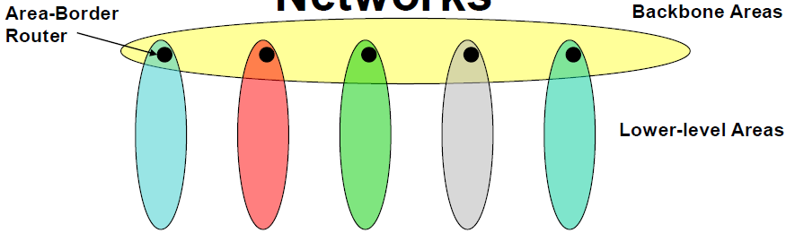
- Within area: Each node has routes to every other node
- Outside area: Each node has routes for other top-level areas only
- Inter-area packets are routed to nearest border router
- Constraint: no path between two sub-areas of an area can exit that area, except they both reach the border router => may no longer have shortest path routes
- Transmit link state advertisements
-
IP Routing (cont.)
- Distance-vector: Nodes construct their own tables iteratively, Each sends information about its table to neighbors
- Link cost changes: “good news travels fast”, bat news travels slow: count to infinity problem (way to solve: split horizon, or, Poison reverse)
- Routing Information Protocol (RIP)
- Every link has cost 1; “Infinity” = 16 - Limits network diameter to 15 hops
- Routers exchange different types of updates
- Initial: asks for copy of table for every neighbor when it starts, to iteratively generate own table
- Periodic: sends copy of its table to each neighbor every 30 sec
- Triggered: send copy of entry to neighbors when entry changes (Except for one causing update (split horizon rule))
- Link State vs. Distance Vector
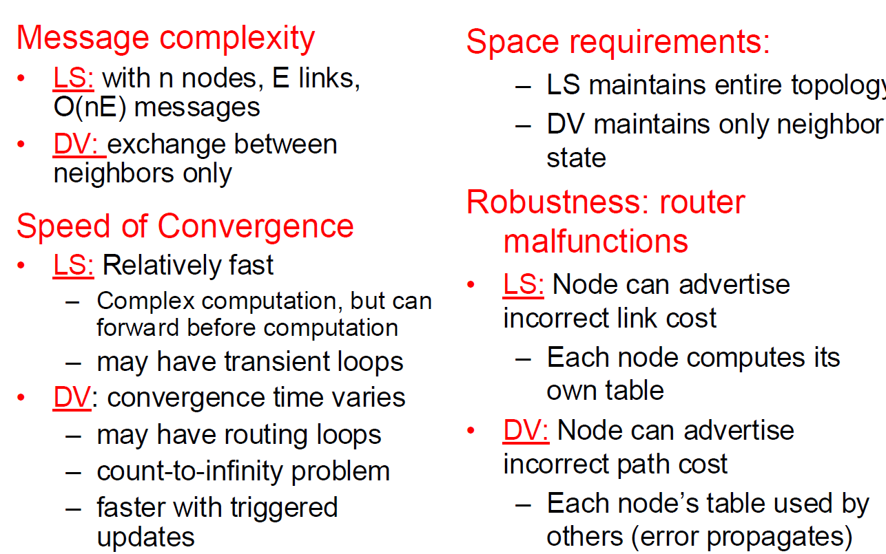
- Distance-vector: Nodes construct their own tables iteratively, Each sends information about its table to neighbors
-
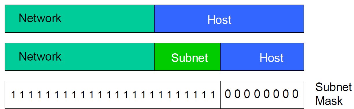
Subnet Mask
- subnet: another layer of hierarchy
- variable length subnet masks
- subnetting is done internally in the organization (not visible outside)
-
Classless Inter-Domain Routing (CIDR)
- Arbitrary split between network & host part of address -> more efficient use of address space
- Merge forwarding entries -> smaller tables
- Longest Prefix Match
- Example routing table:
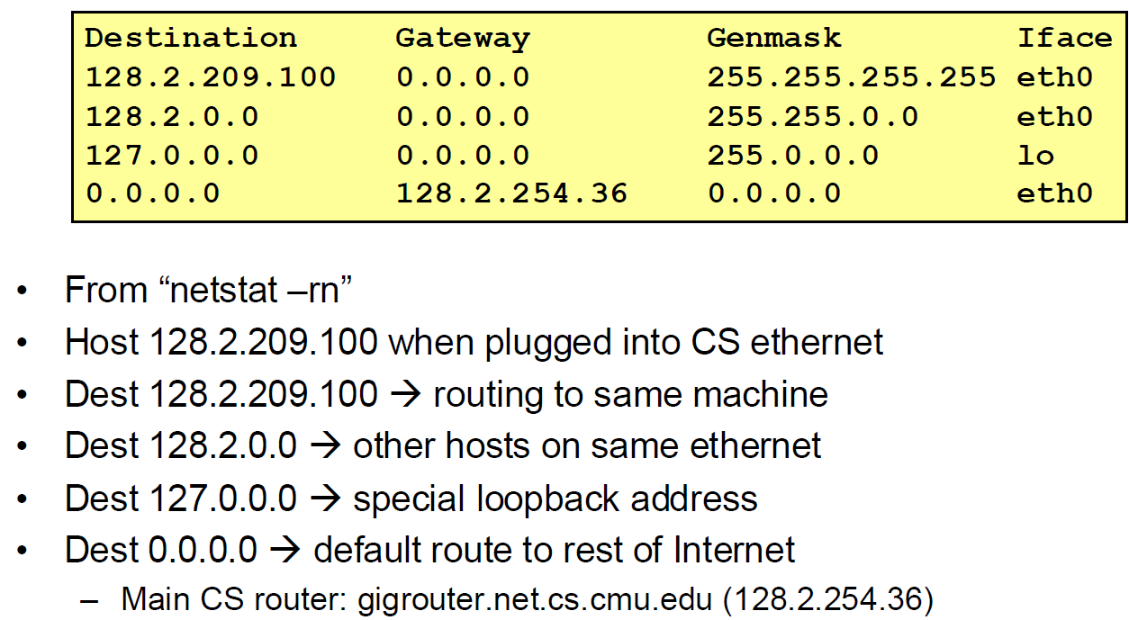
- Example routing table:
-
IP Header
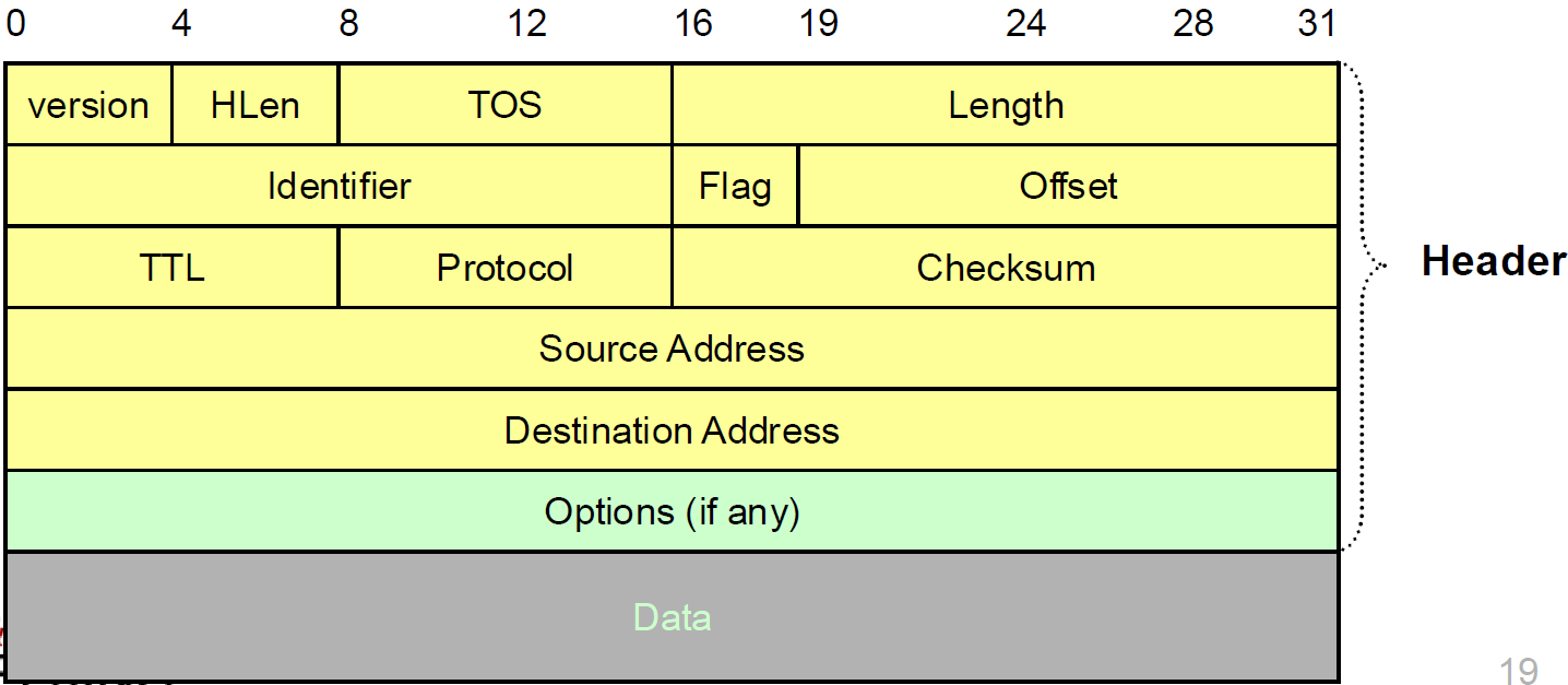
- Version: IP Version, 4 for IPv4
- Header format can change with versions, First byte identifies version
- HLen: Header Length, 32-bit words (typically 5)
- TOS: Type of Service, Priority information
- Length: Packet Length, Bytes (including header)
- Length field limits packets to 65,535 bytes, In practice, break into much smaller packets for network performance considerations
- Identifier, flags, fragment offset -> used for fragmentation
- Time to live: Ensure packets exit the network
- Must be decremented at each router
- Packets with TTL=0 are thrown away
- Protocol: Demultiplexing to higher layer protocols, (e.g. TCP = 6, ICMP = 1, UDP = 17…)
- Header checksum: Ensures some degree of header integrity (Relatively weak – 16 bit)
- Source and destination IP addresses
- Options
-
IP service model
- The Internet Protocol (IP) provides a low-level communication model for transferring data between devices on a network.
- Datagram
- IP is a connectionless protocol, meaning it doesn’t establish a dedicated path or connection before sending data.
- Each packet (datagram) is self-contained and includes all the necessary information (addresses, identifiers, etc.) to reach its destination.
- This is analogous to a letter or telegram, where each message is sent independently, and delivery doesn’t depend on prior setup or subsequent maintenance
-
IP Fragmentation
- Every network has own Maximum Transmission Unit (MTU): Largest IP datagram it can carry within its own packet frame
- When hit network with small MTU, router fragments packet
- Each fragment is treated as an independent packet with its own header
- Destination host reassembles the packet: Routers along the way do not reassemble packets to save processing time and avoid delays
- Fragmentation Related Fields
- Length: Length of IP fragment
- Identification: To match up with other fragments
- Flags: Don’t fragment flag / More fragments flag
- Fragment offset: Where this fragment lies in entire IP datagram, Measured in 8 octet units (13 bit field)
- Fragmentation is Harmful
- Uses resources poorly
- Forwarding costs per packet
- small chunk of data
- Worst case: packet just bigger than MTU
- Poor end-to-end performance
- Loss of a fragment results in loss of the packet
- Uses resources poorly
- To avoid: Path MTU discovery protocol: determines minimum MTU along route
-
NATs (Network Address Translation)
-
Motivation: Original IP model: Each host has a unique public IP address, which create pressure on the address space as every host requires a public IP address. However, Most devices in an organization function as clients and don’t need public IP addresses; A limited number of devices (e.g., mail or web servers) act as servers for the organization => Traffic is routed through a firewall and NAT, reducing the need for public IP addresses
-
NAT: Private IP addresses are assigned within organizations using reserved ranges like
10.0.0.0/8and192.168.0.0/16, NAT translates private IPs to a public IP for external communication.-
using NAT table
-
Client connection:
- OS assigns ephemeral port
- firewall acts as proxy for client: to outside Internet, act as sender of client messages; act as destination for server messages, relabels destination to local addresses
-
Enabling servers:
- Use port mapping to make servers available: Manually configure NAT table to include entry for well-known port
-
-
Benefits
- Prevents internal packets from being routed externally
- often combined with firewalls => Hides internal network details from the outside world => also enhances security
- Little NAT boxes make home networking simple
-
Considerations
- NAT has to be consistent during a session: maintain during session, and recycle after end of session (might be hard to detect)
- NAT only works for certain applications
- e.g. Some applications (e.g. ftp) pass IP information in payload => not suitable
- Need application level gateways to do a matching translation
- e.g. Peer-peer, multi-player games have problems => not suitable, who is server?
-
-
Tunnels
-
Tunneling: Force a packet to go to a specific point in the network
-
Achieved by adding an extra IP header to the packet with a new destination address
-
IP-in-IP Tunneling
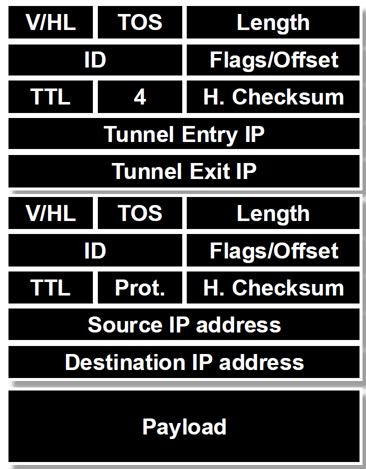
- Protocol id = 4 (IP)
- Several fields are copies of the inner-IP header
- Inner header is not modified, except for decrementing TTL
- applications: VPN (Virtual Private Networks); support for new or unusual protocols: to ‘bypass’ routers that do not support it; force packet to follow non-standard routes
-
Overlay Networks: A network “on top of the network”, Tunnels between nodes on a current network
-
-
IPv6
-
changes from IPv4
- increase address space (128 bit)
- simplify header for faster processing
- no checksum: assume lower & higher layers already perform their own check-summing + Today: corruption is rare, bandwidth is cheap
- no fragmentation: Router discard packets, send ICMP “Packet Too Big” => fragmentation is handled at the source device, which is required to perform path MTU discovery
- Support for guaranteed services: priority and flow id
- Options handled as “next header” – reduces overhead of handling options
-
IPv6 addressing: hierarchical addressing
- Global Routing Prefix (First 48 Bits):
- starts with
010+ Registry (IANA, Regional Internet Registry, etc.) + Provider (ISP or large organization) + Subscriber (Customer or site-specific allocation) - Ensures scalability for global routing, For example, an entire 48-bit block can be allocated to a single LAN (Local Area Network), utilizing Ethernet MAC addresses for ease of assignment
- different chunks for geographical addressing, perhaps help clean up routing tables (e.g. one chunk per ISP)
- starts with
- Subnet ID (16 Bits After Global Prefix)
- Interface Identifier (Last 64 Bits)
- Global Routing Prefix (First 48 Bits):
-
IPv6 Stateless Address Autoconfiguration (SLAAC): Serverless (“Stateless”). No manual config at all
- Link-Local Address:
-
used for communication within the same link (local network). not routable outside the local link
-
used for Router Contact: to communicate with routers for additional configuration, such as soliciting a globally routable prefix
- Usually: Concatenate this prefix with local ID => globally unique IPv6 ID
-
Address Format: Starts with the
1111 1110 10binary prefix (fe80::/64); The remaining 64 bits are derived from the interface’s MAC address or another identifier -
Uniqueness Test: unique within the link
-
- Link-Local Address:
-
-
Translation: ARP Address Resolution Protocol (IP to MAC)
- Broadcast search for IP address (E.g., “
who-has 128.2.184.45 tell 128.2.206.138” sent to Ethernet broadcast (all FF address)) - Destination responds (only to requester using unicast) with appropriate 48-bit Ethernet address (E.g, “
reply 128.2.184.45 is-at 0:d0:bc:f2:18:58” sent to0:c0:4f:d:ed:c6) - Each Host Maintains Cache of ARP Entries with “Soft state”: set timeout of ~20 minutes
- Broadcast search for IP address (E.g., “
-
Translation: DNS Domain Name System (Host to IP)
-
DNS records format
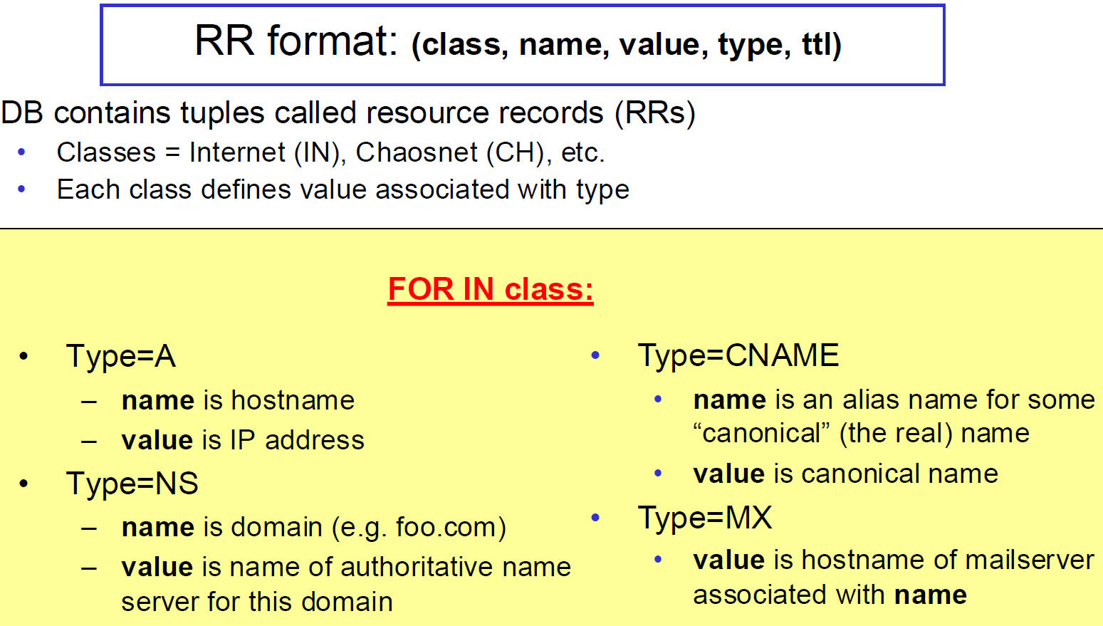
-
DNS message format
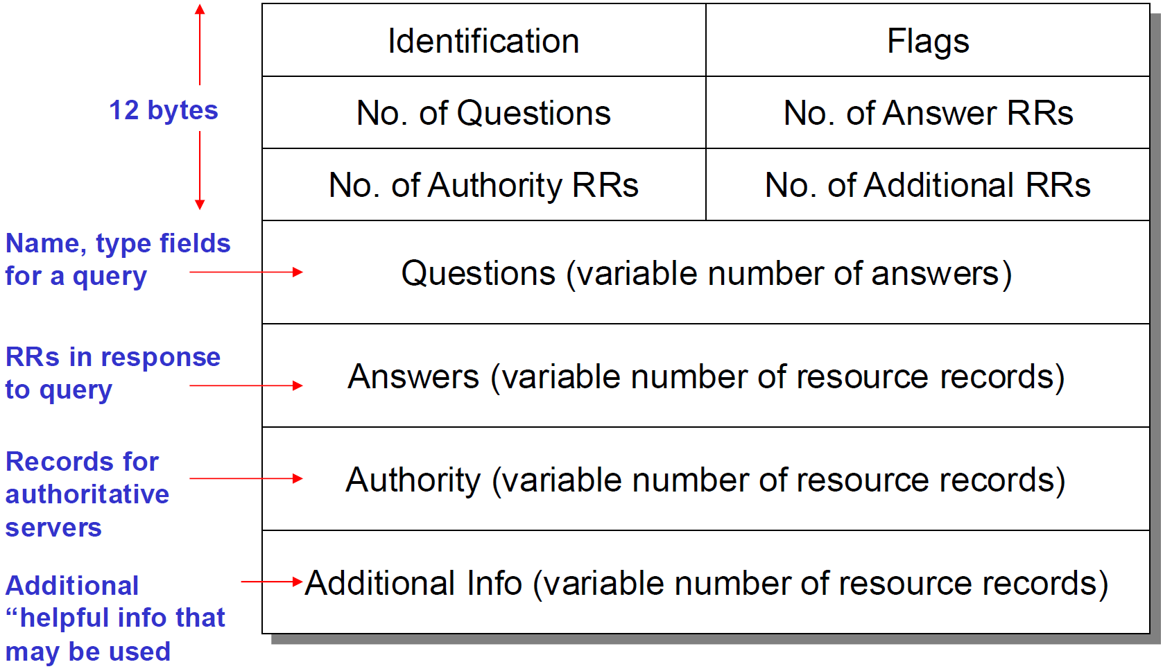
- identification: request/response
- flags: 4 bits
-
application => resolver => local name server => root server etc.
-
recursive (Server goes out and searches for more info) vs. iterative (Server responds with as much as it knows) query
-
cache with time out (TTL)
-
reliability:
- servers are replicated
- UDP used for queries
- try alternate servers on timeout
- same identified for all queries (client doesn’t care which server responds)
-
Lecture 14: BGP
-
Routing hierarchy (zoomed out): Inter and intra domain routing in the Internet
-
Area hierarchy: Autonomous Systems (AS)
- A set of routers under a single technical administration (under unified routing policy)
- using an interior gateway protocol (IGP) and common metrics to route packets within the AS; using an exterior gateway protocol (EGP) to route packets to other AS’s
- Each AS assigned unique ID
- AS’s peer at network exchanges
- AS Numbers (ASNs): 16 bit values (64512 through 65535 are “private”)
-
“Valley-free” routing
- Number links as (+1, 0, -1) for provider, peer and customer
- In any path should only see sequence of +1, followed by at most one 0, followed by sequence of -1
-
BGP Border Gateway Protocol’s routing protocol
- Distance Vector with Path
- Each routing update carries the entire path
- Loops can be detected: When AS gets route, check if AS already in path
- Advantage: Metrics are local - AS chooses path, protocol ensures no loops
- Policy-based routing: Routing decisions are influenced by policies rather than just shortest-path or distance metrics (in AS)
- Interconnecting BGP Peers: BGP uses TCP to connect peers
- Advantages:
- Simplifies BGP
- No need for periodic refresh - routes are valid until withdrawn, or the connection is lost
- Incremental updates
- Disadvantages
- Congestion control on a routing protocol?
- Poor interaction during high load
- Advantages:
- Hop-by-hop Model: BGP advertises to neighbors only those routes that it uses
- Distance Vector with Path
-
BGP Mechanics
- Path vector - scalable, hides structure from neighbors, detects loops quickly
- BGP Messages: OPEN, KEEP_ALIVE, NOTIFICATION, UPDATE
- LOCAL PREF: Local (within an AS) mechanism to provide relative priority among BGP routers
- peering > transit
- customer > peer > provider
- AS_PATH
- LOCAL PREF: Local (within an AS) mechanism to provide relative priority among BGP routers
- Multi-Exit Discriminator (MED): Used when two AS’s connect to each other in more than one place as Hint to external neighbors about the preferred path into an AS
- typically used in provider/subscriber scenarios
- can lead to unfairness if used between ISP because it may force one ISP to carry more traffic
- Path Selection Criteria
- Highest LOCAL-PREF
- Shortest AS-PATH
- Lowest origin type
- Lowest MED (if routes learned from same neighbor)
- e(external)BGP over i(internal)BGP-learned
- Lowest internal routing cost to border router
- Tie breaker, e.g., lowest router ID
-
e-BGP vs i-BGP
- i-BGP: Establish connectivity between routers inside AS
- messages are the same
- I-BGP uses different rules about re-advertising prefixes:
- Prefix learned from E-BGP can be advertised to I-BGP neighbor and vice-versa, but
- Prefix learned from I-BGP neighbors cannot be advertised to other I-BGP neighbors => direct connections (TCP) for I-BGP routers
- Reason: AS PATH is the same in an AS and thus danger of looping.
-
ISPs Peer
- Public peering: use Layer 2 private network to connect
- Private peering: directly connect ISP border router
Lecture 15-18: Transport Layer
1. UDP vs. TCP
- functionality
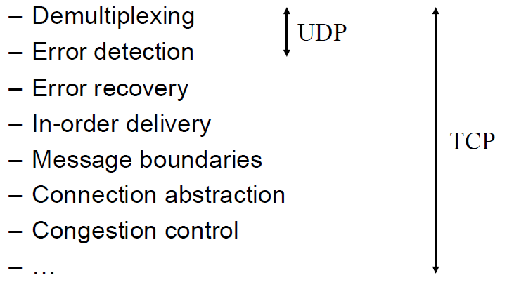
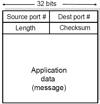
- UDP
- TCP
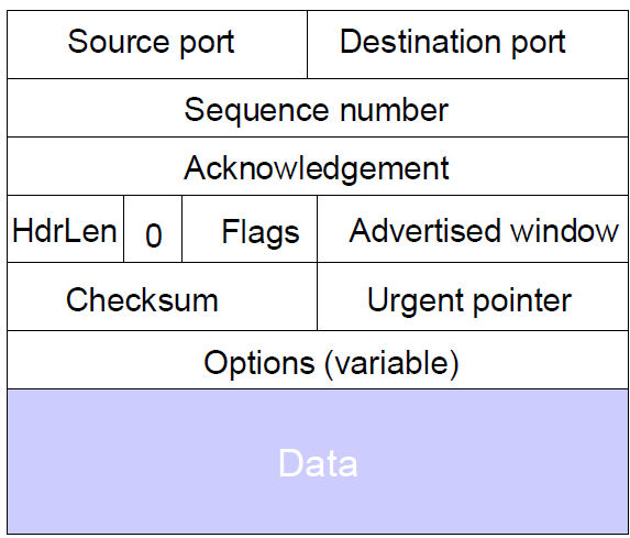
2. TCP Error recovery and flow control
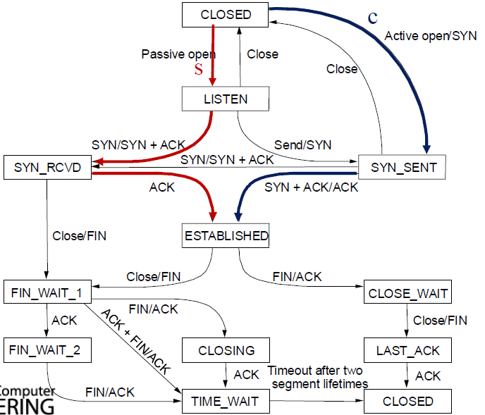
- connection establishment: Three-Way handshake; connection teardown
- TCP state diagram
- ACK and retransmission strategies
- different ACKs
- ACKs acknowledge exactly one packet
- Cumulative acks (CACK) acknowledge all packets up to a specific packet
- Negative ACKs allow a receiver to ask for a packet that is (presumed to be) lost
- receiver: Receiver individually acknowledges correctly received packets. If packets out of order, receiver cannot hand data to application so window does not move forward
- sender: Sender only resends packets for which ACK not received. Sender timer for individual unACKed packet
- TCP = Go-Back-N Variant
- sliding window with CACKs, but sender only retransmits a single packet
- Fast Retransmit on 3 Duplicate ACKs
- Problem: multiple losses - each wait for timeout, slow
- basic problem is that CACKs provide little info
- to solve: TCP option: SACK (selective ack) adds a bitmask of packets received, encoded as a set of received byte ranges
- retransmit: A common rule is to wait for the missing packet to be out of order by 3 packets before triggering a retransmission
- different ACKs
- RTT estimation
- usage: wait at least one RTT before retransmitting
- RTTs exponentially averaged: New RTT =
(old RTT) + (1 - ) (new sample), =0.875 for most TCPs - Retransmit timer set to (b * RTT), where b = 2 + exponential back-off
- Problem: spurious timeouts
- Jacobson’s Retransmission Timeout: adaptive mechanism where the RTO (Retransmission Timeout) is calculated based on both the estimated RTT and its variance
- Key observation: At high loads, round trip variance is high
- Solution: Base RTO on RTT and standard deviation: RTO = RTT + 4 * rttvar
- new_rttvar =
* dev + (1- ) * old_rttvar - Dev = linear deviation
- Jacobson’s Retransmission Timeout: adaptive mechanism where the RTO (Retransmission Timeout) is calculated based on both the estimated RTT and its variance
3. TCP congestion control
- Congestion Collapse: Increase in network load results in decrease of useful work done
- end-to-end congestion control (TCP’s approach) vs. network-assisted congestion control
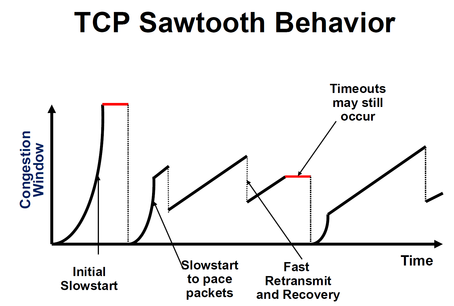
- Implicit Feedback and AIMD
- + fast retransmit
- + slow start: Upon receipt of every ack, cwnd = cwnd + 1
- allows TCP to quickly find a good window size i.e. Reaches W in
- allows TCP to quickly find a good window size i.e. Reaches W in
- Fast Recovery
- Observation: each duplicate ack notifies sender that a single packet has cleared the network
- When
< new cwndpackets are outstanding, Allow new packets out with each new duplicate acknowledgement - This keeps the sender active while avoiding overwhelming the network, thereby maintaining the flow of data
- behaviour
- e.g. Sender is idle for some time waiting for 1/2 cwnd worth of dupacks; Transmits at original rate after wait with ack clocking
- e.g. immediately after a multiplicative decrease post fast retransmit, TCP increases
cwndby 1/W every alternate ACK
4. TCP optimizations
- buffer at router
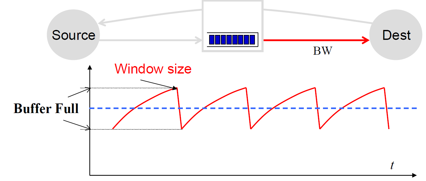
- buffer should hold enough data to keep pipe full
- to achieve full link utilization: Buffer Size = Height of TCP Sawtooth = BW x RTT
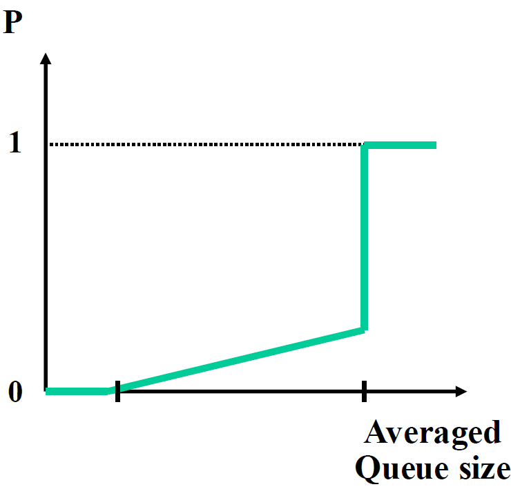
- Random Early Detection (RED): Start randomly dropping packets before queue is full
- Explicit Congestion Notification (ECN): provide explicit congestion notification to senders
- The ECN-Capable Transport (ECT) bit is set by the sender to indicate that the endpoints are ECN-capable
- The Congestion Experience (CE) bit is set by the router to signal congestion
5. TCP performance
- bandwidth: BW = 3/4 W (packets / RTT) = 3/4 W * MSS / RTT
- loss rate: p = (1 packet lost) / (3/4 W / RTT * (W/2 * RTT) packets transmitted) = 8 / 3W
=> W = - => BW =
- TCP is RTT fair
Lecture 18: SDN & OpenFlow
- Software-defined Networking (SDN)
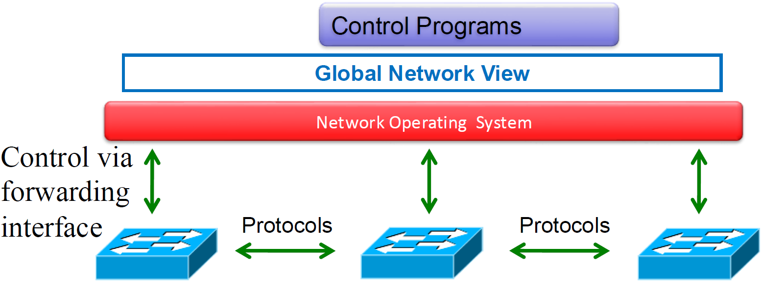
- idea: an OS for networks
- No longer designing distributed control protocols
- OpenFlow
- Standard way to control flow-tables in commercial switches and routers
- Just need to update firmware
- Essential to the implementation of SDN
Lecture 19: Security
-
Secure communication channel: Authentication, Confidentiality, Integrity, Non-repudiation + Availability
-
Symmetric Key Crypto
- One-time Pad (OTP) is proven “information-theoretically secure”
- but: Key is as long at the message; Keys cannot be reused
- Cryptographic Hash Functions
- Consistent: hash(X) always yields same result
- One-way: given Y, can’t find X s.t. hash(X) = Y
- Collision resistant: given hash(W) = Z, can’t find X such that hash(X) = Z
- Confidentiality: Stream & Block Ciphers
- Integrity: HMAC (Hash Message Authentication Code)
- Authentication: HMAC and Nonce
- One-time Pad (OTP) is proven “information-theoretically secure”
-
Asymmetric Key Crypto
- Confidentiality: Encrypt with Public Key of Receiver
- Integrity: Sign message with private key of the sender
- Authentication: Entity being authenticated signs a nonce with private key, signature is then verified with the public key
-
Symmetric key distribution: Key Distribution Center (KDC)
-
KDC: server shares different secret key with each registered user (many users)
-
For Alice and Bob to get symmetric key:
- Alice, Bob know own symmetric keys,
, for communicating with KDC 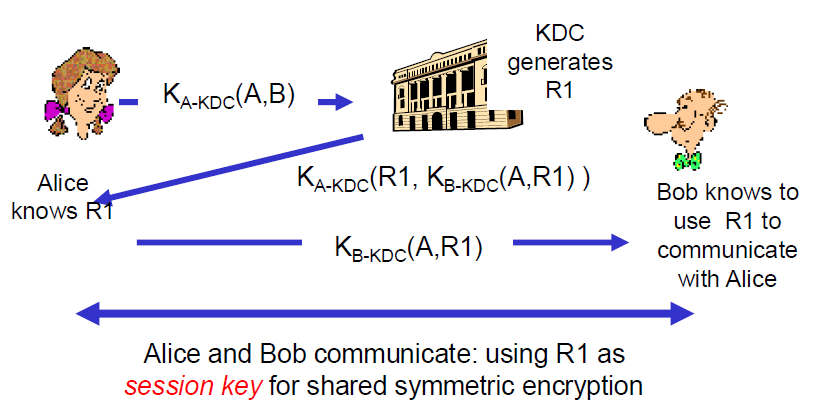
- Alice, Bob know own symmetric keys,
-
Limitations
- Must be always online
- KDC can expose our session keys to others
- Centralized trust and point of failure
- In practice, the KDC model is mostly used within single organizations (e.g. Kerberos) but not more widely
-
-
Certification Authorities (CA)
- CA: binds public key to particular entity E
- E registers its public key with CA, and certificate contains E’s public key AND the CA’s signature of E’s public key
- When Alice wants Bob’s public key: (1) Gets Bob’s certificate (Bob or elsewhere), and (2) Use CA’s public key to verify the signature within Bob’s certificate, then accepts public key
- CA: binds public key to particular entity E
-
Transport Layer Security TLS
- Special TLS socket layer between application and TCP (small changes to application)
- Handles confidentiality, integrity, and authentication
- Handshake Steps:
- Client and server negotiate exact cryptographic protocols
- Client validates public key certificate with CA public key
- Client encrypts secret random value with server’s key, and sends it as a challenge
- Server decrypts, proving it has the corresponding private key
- This value is used to derive symmetric session keys for encryption & MACs
-
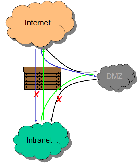
Typical firewall configuration
-
Tor Anonymity Network
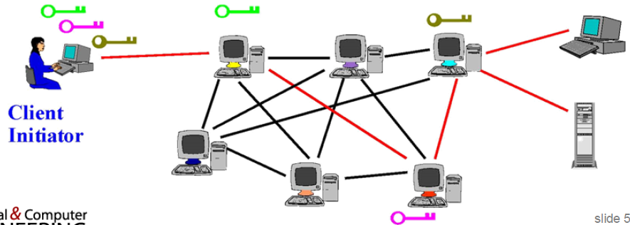
- Client applications connect and communicate over established Tor circuit
- Using Tor: Many applications can share one circuit
- Multiple TCP streams over one anonymous connection